The Smartisant Arduino Shield SHLD1 exposes 6 analogue pins (A0 to A5) and these can be used as both analogue and digital inputs or as digital outputs.
It also exposes 8 digital IO pins (pin 2 to pin 9) via a 10-way shrouded header connector and these can also be used as both digital inputs or outputs. Some of the pins are also PWM capable and a few of the pins can be configured to use interrupts.
The PCB exposes two power connectors. On V3, there is a 2-pin connector exposing Vin and GND. The Vin goes to the Arduino's on-board voltage regulator and can be a dc voltage between 6.5V and 12V. We don't advise powering Arduino devices with higher voltages though, as the regulator can get hot and fail. Typically, we use a local dc-dc convertor set to around 8V dc.
The second connector also exposes the 5V dc and 3.3V dc power rails on the Arduino. It is possible to bypass the Arduino's on-board regulator and apply a regulated 5V dc power to the 5V pin. If a local dc-dc convertor is used, this can allow many 5V sensors and devices to be powered, as well as the Arduino processor. This is our preferred approach with the Arduino Uno, Arduino Mega 2560 and the Mega 2560 Pro.

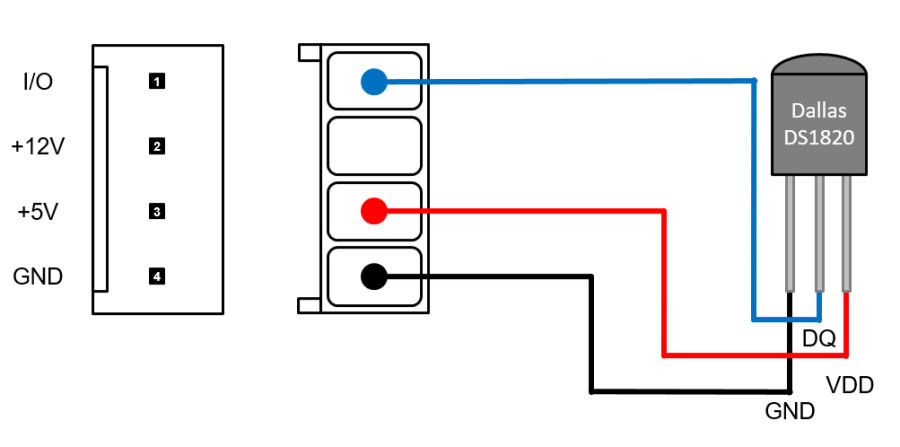
When connecting a Dallas DS1820 1-Wire temperature sensor, the analogue input A0 should be used as the shield is designed to simplify connection of 1-Wire devices using this input and incorporates a space for the required 4.7KΩ resistor.

One or more (connected in parallel) DS1820 temperature sensors would be connected using a 4-way Molex connector like this. There is no 4.7KΩ resistor required if it is fitted to the shield PCB and using the A0 input.

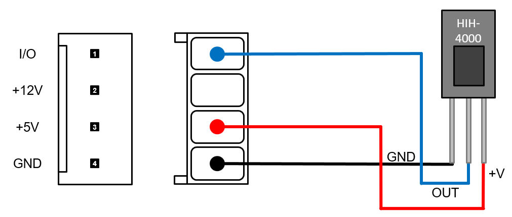
When connecting a Honeywell HIH-4000 series humidity sensor to one of the analogue inputs only the 0.1µF capacitor is required. To measure relative humidity, you will also need to know the temperature.

An Honeywell HIH-4000 series humidity sensor would be connected like this. The leads need to be kept fairly short (less than 20cm) and no resistor is required as the Arduino inputs are high impedance. There is space for the required 0.1µF capacitor on the PCB next to the 4-way header.

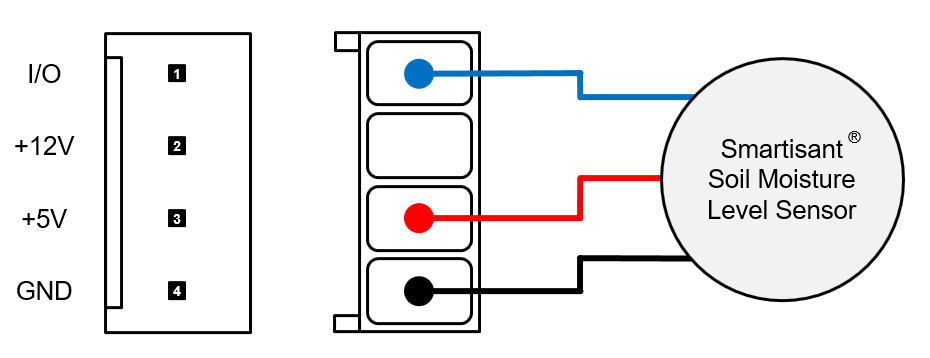
The Smartisant Soil Moisture Level Sensor SML1 would be connected like this to one of the analogue inputs.
Code examples are provided with the Smartisant Soil Moisture Level Sensor SML1 application notes.

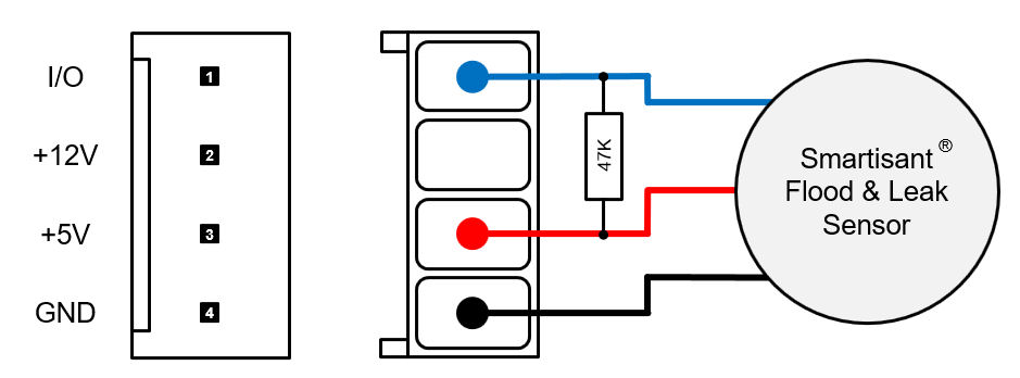
When connecting a Smartisant Flood & Leak Sensor FLD1 to one of the digital inputs, a pull-up resistor is required. If using the Smartisant 8-channel IO Board IO1 then this can be installed on the Smartisant 8-channel IO Board IO1 PCB.
When using 12V sensors, you need to use a suitable interface board to deliver the 12V power to the 4-way Molex connector and to convert the 12V signals to the required 5V logic. This can be achieved using either the Smartisant 8-Channel Fused Input Board IP1 or the Smartisant 8-Channel 12V Input Board IP2. This then enables much more reliable signalling over long wires and also enables a much wider range of 12V sensors to be connected.

We recommend 12V is used for door contact sensors in the smart home because it is more reliable and much less prone to external interference. With the door closed, the reed switch would also be closed, resulting in 12V being applied to the 12V input.
The connection of Passive Infra-Red (PIR) sensors is a project on our Dream Green House website.
The connection of smoke sensors is a project on our Dream Green House website.

We recommend 12V is used for window contact sensors in the smart home because it is more reliable and much less prone to external interference. With the window closed, the reed switch would also be closed, resulting in 12V being applied to the 12V input.
When measuring dc voltages using the analogue inputs, it is best to fit the associated 0.1µF capacitor. If you want to measure voltages higher than those allowed on the analogue input ports, then you will need to use a voltage divider.